"ANNUALIZED GEO-SOLAR HEATING" AS A SUSTAINABLE RESIDENTIAL-SCALE
SOLUTION FOR TEMPERATE CLIMATES WITH LESS THAN IDEAL DAILY HEATINGSEASON SOLAR AVAILABILITY
Don STEPHENS, InA
Private Eco-shelter Design Consultant, Author, Teacher, Mentor and Alternative-construction Innovator,
P.O.B. 1441 Spokane WA 99210-1441 USA www.greenershelter.org , don@greenershelter.com
Vice President and Founding Member, Inland Chapter, Northwest EcoBuilding Guild
Architectural Advisory Board, Spokane Falls Community College, Spokane WA USA
Keywords: residential design, sustainable, annualized solar heating, geo-solar storage, time-lag, perimeter
insulation, AGS
Summary
Although the sun would, at first thought, seem a most sustainable source of cold-season building warmth for
temperate climates, in many such regions its actual daily surface availability at those times of year is
unreliable, at best. In these places, the traditionally advocated "short-cycle" solar techniques, dependent on
DAILY cold-season radiant input through glass and using limited amounts of in-structure mass as storage,
have failed to provide effective solar fractions. This paper discusses a relatively simple and low-cost, but far
more reliable alternative and supplemental strategy of solar capture, storage and return for those conditions,
based upon ANNUAL, rather than daily, intervals.
In this case the far more predictable and plentiful SUMMER sun is the energy source which is tapped by any
of a range of isolated collectors, low-velocity air is the typical transfer medium. Existing earth beneath the
structure serves as the storage mass, while also facilitating a predictable and extended time-lag. As a result,
peak delivery of that energy, up through the floor by conduction, only occurs six months later, when most
needed to maintain WINTER warmth.
For sub-structure soil to reach and maintain optimal temperatures (a several year process), it must be
buffered from winter's outdoor extremes by sub-grade perimeter insulation extensions and from precipitationtransferred losses by perimeter water-diversion devices. Also, to maximize the system's efficacy in a given
building, exposed portions of its shell must be constructed tightly and with high insulation values. (And to
also best address other sustainability goals, such building-materials and insulation need also be chosen
which offer best compromises between the renewable, durable, non-toxic, locally available and/or those
plentifully salvageable from the so-called "waste-stream".)
This "technique assemblage" of summer heat collection, sub-structure storage with designed-in time-lag,
winter return, and perimeter restriction of system losses, is what I have come to term "Annualized GeoSolar" or AGS. It has been progressively developed and tested over more than thirty years in the inland
northwestern portion of the United States, and continues to evolve, as knowledge of its methods is now
being dispersed world-wide.
1. Background and History
Methods of "annualized" heat management actually go far back into human pre-history. Humans have
continuingly sought better ways to limit bodily heat losses and gains, in response to our species' rather
narrow comfort range. Shelter choices which support this are a recurrent theme throughout human prehistory and history, in all cultures. And in a range of ways we have utilized techniques which bring solar
energy from seasons of plenty into seasons of short supply
1.1 Early Human Shelter and Annualized Heat Management
Since that time when earliest bands of humans first left the tropics and ventured out into more temperate
regions, their very survival has been dependent upon how well they were able to maintain core body heat in
cold periods. Their probable first responses would have been at conserving bodily warmth by insulative
clothing. But early on, shelter also proved an obvious and effective second line of defense against weather
extremes, as confirmed by ancient middens in rock shelters and caves. And, though the underlying reasons
may well have been beyond their explicit understanding, it would have been immediately obvious that
deeper caves were far cooler in summer and warmer in winter than mere overhangs or improvised shelters.
Looking back now, we can see that this was because, beyond the first few feet at the entrance, such in-the-earth spaces reflected an average of all the local yearly highs and lows outside. In other words, they
presented an "annualized" temperature.
Data indicates that as far back as 1.5 million years ago, humans began bringing fire into those caves (Levin,
2005). They probably didn't realize that, in addition to the immediate warmth and cooking benefits they
derived, they were also slowly raising the holding temperature of the rock and earth masses around them.
Beneath the fire’s coals, heat was slowly conducting down and outward, radiant warmth was reaching
surrounding surfaces, and pools of heated air at ceiling level were transferring their energy to the rock mass
above. And these fires, fueled primarily by the summer growth of tree bulk, were turning that stored energy
into winter heat, while simultaneously increasing the annualized temperature of the surrounding earth mass.
But early humans did not live by warmth alone. They also required nearby sources of food and water, and
sought other resources to support their expanding skills in fabricating tools and other elements of their
material culture. Caves were not always located handily to such sources. And often those resources,
themselves, were so scattered as to necessitate a seasonal round of travel. So sometimes shelters in those
locations must be improvised, and were.
However, archeological research would suggest there was always the longing to somehow bring to those
surface shelters the benefits of cave-like thermal annualization. From the northern islands of the Japanese
Archipelago and the shores of the Arctic Ocean, through the temperate zones and even in mountainous
parts of subtropic regions, in both hemispheres, muro, kivas and other "pit-houses" (consisting of more-orless insulated superstructures, covering several-foot-deep "floor" excavations into the soil, often with earth
berming at least part-way up the sides) show up time and again, in a wide range of cultures, as an all-year or
winter dwelling strategy. This approach combines the benefits of greater resource-determined placement
choices, with the protection and thermal moderation provided by more earth-integration. And with a burning
hearth or fire-pit maintained (as it typically was) in or near the center of such a one-room space, it's radiant
energy, and the air warmed by it, are contained by the constructed super-structure, and the conducted heat
from its coal-bed spreads slowly outward through the high-mass floor, as it did in caves, assuring steady and
continuing warmth beneath the surrounding sitting and sleeping areas. (Some such fire-pits even had subfloor ducting to bring in combustion air, while reducing drafts within the living space itself.) (Maxwell, 1978)
A commonly-seen further "evolution" of this was the use of earth and/or stone to construct thick above-grade
walls (and in some cases, vaulted or domed roofs), resulting in even greater cave-like absorption mass.
This has proven to work so well, in a variety of climates, that even today, over one third of the planet's
population still lives in such houses of earth, some as much as ten stories tall and more than a thousand
years old (Dethier, 1981; Steen, 2003), and a near-similar number live in masonry structures of brick and/or
stone. In climates enjoying daily cold-season sun, this kind of structural mass also serves as a kind of
simple "trombe wall", providing solar warmth-delivery delayed until needed at night (Mazria, 1979).
Other traditional pieces of the heat-conservation puzzle, including high levels of insulation in exposed
building shell elements, also saw technological evolution through the ages, in more demanding climates.
Prehistorically and pre-industrial-revolution this was commonly realized through thick straw-and-reed thatch
or bark-and-sod on roofs and with wood, sawdust, clay-stabilized grasses, and/or woven reed-mats in walls,
among other materials. And to permit light penetration, while restricting related infiltration, oiled skins,
animal intestine, waxed papers or even ice, preceded the use of glazing. (Maxwell, 1978)
1.2 The Non-Sustainable Fossil-Fuel “Distraction”
While the combustion of wood, grasses and animal dung offered (at least when populations were low and/or
resources well managed) sustainable ways of harvesting summer's stored energy for winter warmth, the
adoption of fossil fuels for space tempering was, from its beginning, clearly a gross diversion from this
important principle.
But none-the-less, early dependencies, first on peat and then on coal, as fuels, were followed, in more
"modern" times, by heavy use of oil and "natural gas" for this non-durable purpose. And so, for a time, our
species has casually squandered these precious resources at an ever-increasing rate. Since the first
commercial oil well began operation less than 150 years ago, the world has burned its way through over 900
billion barrels of this finite resource, using ever more through the years, until what has now become a global
82 million barrel-a-day, or 30 billion barrel-per-year addiction (Pitt, 2005). Of this, 6% (or 1.8 billion barrelsper-year!) is consumed for building heating alone! (Mackenzie, 2000) .
As far back as the 1950s, American school children were being told that there would be a point, within their
lifetimes, when little of this petroleum bounty would remain (personal recollection), but they were then
reassured that the energy shortfall would easily be taken up by the "Friendly Atom" (Disney, 1956). Today,
the public's image of that alternative has become a bit "soiled". Meanwhile, increasing numbers of georesource experts are discussing “peak oil” and “peak natural gas”. These terms apply to the points at which
the rate of discovery of new reserves of these resources are no longer sufficient to replace depletion of
known sources. Most indicate that, if such peaks have not already passed, they soon will be. (MacKenzie,
2000) At the same time, even in America, there is increasing public recognition that our rate of use of these fossilbased resources is also leading to serious climate impacts and that they need to be replaced by renewables,
despite denials by those in high office, whose motives are also increasingly questioned. (Cronkite, (2004, &
PIPA, 2005) So the pressures to re-focus on sustainable strategies for building heating are being
increasingly viewed as necessity.
1.3 Short-Cycle Solar Heating
When I entered architecture school (1959-64) the faculty was happily teaching that the "modern" way to
"condition" large, high-rise buildings was with both furnaces and air conditioners operating continuously, day
and night throughout the year, and then distributing the resulting heated and cooled air through insulated
ducts, to localized mixing units for individual areas of each floor, which there combined the two, to sustain an
ideal thermostat setting in the glass-walled spaces. Those mentors were truly at a loss to understand my
bizarre interest in utilizing solar energy for my student designs (as they were with my "earth-integration" of
them and use of what we now term "green" or "living" roofs....to them, I was just "covering up the
architecture".)
I like to think that, with the "Energy Crunch" of the 1970s, they gained new insights on the reasoning behind
this "madness". By then, active solar techniques, involving the pumps, valves, sensors, fans, storage tanks
and rock-bed vaults so popular with the mechanical engineers, were already beginning to give way to more
passive approaches. A new vocabulary spoke of "direct, indirect, and isolated gain", of "window orientation,
glass-to-mass ratios, and sun angles". And solar fractions were the measure of success. Designers in
regions where "cold and clear" was the typical description for winter weather, were showing great success,
and in more unpredictable and northern climes, vapor barriers and so-called "super-insulation" were coming
into vogue. But among those of us still struggling to produce optimal results for our clients with these
techniques, in regions "blessed" with extended winter cloudy periods, a few longed to somehow tap the
warmer and more predictable summer sun.
1.4 ANNUALIZED Solar, and “the Earth-Sheltering Connection”
Rarely does a new idea arise full-blown, on its own. Far more often, it evolves out of needs and previous
thinking, as so aptly explained by James Burke in his PBS series, "Connections". And as Mr. Burke also
demonstrated, when a need is great, similar solutions often arise from several innovators almost
simultaneously. So it was with Annualized Solar Technology. It arose, "hand in glove" out of new
explorations a number of us were making of earth-sheltering as an energy-management strategy. While I
had been designing structures built into the ground since the 1960s (out of a desire to blend them with their
sites, preserve natural beauty and increase occupants security from extremes of weather, fire and other
threats), the ' 70s energy crunch gave new focus to those efforts. It was one obvious way to minimize
infiltration and there was a commonly held belief that earth was a "good insulator". As a result "building
underground" caught the attention of the media and the public imagination. A number of books were
published on the topic, Earth-Shelter Digest (magazine) hit the news-stands, and the University of
Minnesota's new "Underground Space Association" pursued research on the topic, published a series of
excellent books on underground and earth-sheltered design and launched a schedule of major conferences
across the USA, asking me to be a part of the west-coast program in Portland, Oregon (U. of Minn., 1978), .
It soon became apparent, among earth-sheltering's design professionals, that mineral soil really wasn't a
very "good insulator". Rather, its greatest value was as mass, resisting fast temperature changes. Another
commonly-held myth was that "the underground is "50 degrees F. everywhere" (10 C.). But well-water
temperature maps soon proved that wrong (Labs, after Collins, 1975). Just within the contiguous United
States, for example, temperatures (at depth) ranged from below 40 F.(~ 4 C.), near the Canadian border
mid-continent, to almost 80 F. (~26 C.) in southern Florida. And those figures were for soil "at depth", a
figure which only stabilizes about 20 feet (~6 meters) down. Above that, the swings widen toward the
surface, more closely reflecting first seasonal and then daily average readings. Various agricultural research
has shown that fluctuations within a given day/night cycle don't manifest until 3 to 6 inches (7 to 15 cm)
below soil surface.
So if that soil mass were below indoor comfort temperatures, it represented a continuing heat-sink, drawing
warmth from the building. This led to a designer theory that underground structures should be insulated from
the earth around them. But experience soon suggested otherwise. We found that while an insulated earth
shelter did immediately perform better than a surface structure, requiring less energy for winter heating (and
summer cooling), it's winter performance continued to improve through the first 3 to 4 years. The conclusion
shared by many earth-sheltering researchers was that, even with the insulation between, some heat from
inside was still getting through to slowly warm the surrounding earth, and that as it did, the delta-T (the
difference between inside air and outside in-soil temperature) became smaller, so less additional heat was
being lost.
But several of us also reasoned that this improvement would only occur in the building-protected soil under
the floor. This was because, where precipitation (rain and snow-melt) was soaking into and cooling the earth
on the sodded roof and absorbing accumulated heat, no warmth build-up could persist. And as water trickled down through the building-warmed soil adjacent to the structure's walls, it would capture that warmth
and carry it on down to the water-table, leaving the earth through which it passed at about the rain/snow-melt
temperatures. So to further improve performance, a protective sub-grade membrane was needed, extending
on outward from the roof for some distance, so that the soil beneath it would remain dry and protected from
moisture trickle-down.
A next logical step was to consider some insulation repositioning. It was reasoned that, if the under-floor
insulation were removed elsewhere, the floor-to-earth link would be improved, allowing summer solar gain
through windows to be absorbed more readily by the mass of the soil beneath, helping the structure to resist
tendencies to summer over-heating. And then, in winter, that heat could also return up through the slab
more easily, to help the structure resist cooling from window heat-losses. And, if that removed insulation,
along with what had been against the sub-grade walls, was "swung up" to lay just beneath the abovediscussed extended sub-grade perimeter moisture-diversion membranes, even more protected earth mass
would be available to easily store and exchange warmth with the building's interior. This idea gained
broader exposure when it was discussed in the University of Minnesota's 1978 book, Earth Sheltered
Housing Design: Guidelines, Examples and References (ibid.). This kind of thinking was the basis for a
number of schemes independently innovated, in various locations around the world, for planned applications
of annualized solar. Nearly all of these, in one way or another, utilized the on-site earth as storage medium.
Several innovators also tapped its potential as a predictable time-lag device.
1.5 A Range of Annualizing Approaches
During the 1970s, in the US state of Utah, with its hot summers and severe winters, science teacher and
solar pioneer Daniel Geery was exploring ways to grow vegetables year around, through the use of a sunken
pit-greenhouse, and his resulting book on the subject called for sub-grade perimeter insulation extending out
around the "pit" (Geery, 1982). Thus, when solar heat streamed in through the glazed greenhouse roof,
much of it was absorbed by the pit's floor and walls and several feet of the protected earth beyond,
preventing plant-wilting due to over-heating. And at night and during cold weather, as heat from the pit was
lost to the sky, that stored in the surrounding earth-mass re-radiated inward to maintain air temperatures. So
summer sun contributed to winter warmth. Whether explicitly called that or not, the result was, in fact,
"annualized" solar.
About the same time, other designers in a number of temperate regions were beginning to experiment with
earth-linked, double-shell house designs, also variously known as "envelope houses", "convective loop
designs", or "C-loops", for short (Butler, 1978, Booth, 1980). These typically have a continuous air-flow loop
or buffer zone around the inner living space, incorporating a sunspace between inner and outer glazings as
part of the sunward sloped or vertical wall, a double roof and double walls with air-flow between (at least on
the "poleward" side) and some sort of earth-connected bottom of the loop, below.
The theory was that, on sunny days, as sunspace air became warmer (and thus lighter) it was displaced up
into the space between the double roofs by colder air below, cooled a bit there and slid down between the
double poleward walls and into the under-floor space, where it lost more of its warmth into soil or basement
walls and then moved back up through vents or between-board cracks in the sun-space deck to be warmed
again. At night, on the other hand, as heat was lost out through the sunspace glass, it cooled there, and
becoming heavier, spilling down into the under-floor space, where it extracted warmth from the earth and
having thus become lighter, was pushed up through the poleward wall's air-flow channel, reversing the flow.
In reality, actual flows proved to be much more complex, but none-the-less the sunspace to earth link did
work and the houses proved very efficient (if a bit expensive to build with their double shells, and a worry to
some fire departments and building officials.) And over time, they worked even better, as the summer airflows increasingly warmed the earth beneath them, which came back as greater winter warmth....the solar
was performing on both a daily and an annualized basis.
And for my clients, I was developing designs which took this loop idea several steps further, by integrating
aspects of the envelope concept with my own previous experiences. This resulted in earth-sheltered C-loops
with perimeter subgrade insulation "capes", which proved to work even better, with much greater annualized
effect (personal observations and testing).
In Montana, meanwhile, physicist John Hait was researching the use of sod-covered sub-surface insulation
"umbrellas" (also incorporating diversion membranes) over several feet of earth on the roofs of his concretestructured dome designs, and extending that umbrella outward for twenty feet into the surrounding berms.
This latter was to prevent summer-stored heat in the concrete's mass and the soil around the house, from
"short-cutting" up to the surface the following winter. Instead, it remained available to radiate back inside,
keeping indoor spaces warm. He decided on this extension distance, based on that previously-mentioned
ag-data, indicating soil temps 20 feet (~ 6 meters) down remained annually stable. He termed this technique
(powered by direct solar gain through windows and stored by the high-mass concrete structure) Passive
Annual Heat Storage or PAHS (Hait, 1983).
Half a world away, in Australia, another family of design innovators was taking a still different approach. For
inspiration, they drew upon the desert experiences of opal miners of Coober Pedy. These hardy souls had
started out living in tents on the surface and digging tunnels to find the gems, then noted the tunnels to be so much cooler in summer and warmer in winter, so now "live in their tunnels". And since one spot there is as
likely to be good for finding opals as another, they've learned to carve out their mines into the various roomshapes in which they'd like to live. With earth roofs about 10 feet thick (~ 3 meters) overhead, they get
summer warmth finally migrating down through the ceiling in winter and then being drawn back toward the
surface by the next summer, for all-year comfort. So this observing family of designers began replicating the
effect by specifying in their home designs, massive concrete roof "planters" containing at least 6 feet of
planted earth (~ 2 meters). This gave them a different slant on annualizing (but one which would tend to
work best only in low precipitation climates, where soil-wetness would not corrupt designed-in time-lags
(Baggs, 1999).
For my own part, in the US inland northwest, I was slowly evolving another, and I believe, preferred system,
and one better suited to the waterproofed, wood-structured underground homes I'd found more economical
to implement, easier for owner-builders to construct, and with far lower eco-impact than concrete. I sought
to provide greatest reliability with minimum initial cost, and with maximum material and design flexibility,
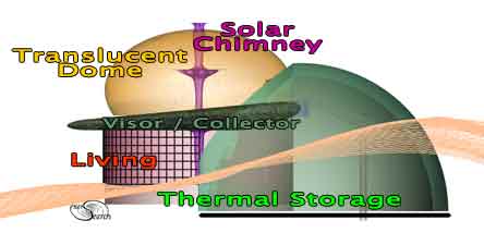
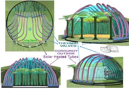
without compromising performance. The basic idea is conveyed by figure 1 below:
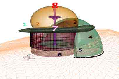
Figure 1 Figure 2
The result is a system utilizing sun-heated air as its in-soil distribution medium, passed through inexpensive
polyethylene flex pipe. It takes advantage of an extended and predictable time-lag which naturally occurs
when spring, summer and fall-deposited warmth disperses through defined distances in the dry, substructure earth. This heat, traveling either vertically from deep below the floor, or a similar distance
horizontally directly beneath sub-slab insulation, reaches uninsulated conductive floor areas six months later
(See figure 2 above). Here it then radiates from floor surfaces, up into living spaces, in response to the
minimized indoor, cold-season heat-losses through windows and other surfaces. Although it takes several
years (the number varying, due to differences in ratios between feasible collector size and output, indoor
conditioned cubic footages and overall envelope insulation levels), when the soils do reach optimum
temperatures, this system plus incidental indoor activity heat-inputs (from people, lights, cooking, other
appliances, etc.) can provide, in winter-cloudy climates, an otherwise unattainable 100% solar heating
fraction.
But to be that energy effective (as well as eco-appropriate), the structure must also have a very wellinsulated envelope of renewable, healthy, recycled and/or salvaged-from-the-waste-stream materials, and
be detailed to minimize infiltration losses, in it's weather-exposed portions. For this, I choose planted-earth
or metal roofs (with strawbale or poured-in rice-hull insulation), and straw-bale, tire-bale, or ricehull-bag walls.
As a result, each design also sequesters, for the life of the structure, a number of tons of carbon. And
windows of highest performance standards, with PVC free-frames, also need effective manual or automatic
night insulation, to reduce heat losses in coldest periods.
Also, as figure 2 suggests, I’ve now adapted this approach to more conventionally-roofed and fully surfacebuilt homes, as well. In either case, because I rely on the more-controllable, isolated-gain, solar capture
sources (sunspaces, greenhouses, thermosyphon collectors or "tuned" plenum spaces beneath any
exposed metal roof surfaces), windows and unbermed walls can remain under deep overhangs, precluding
the potential for summer over-heating and UV damage to furnishings, which are inherent in some other
approaches. In alternative-building circles and internet discussion groups, this unique solar technique has
come to be called AGS (short for Annualized Geo-Solar).
2. What ANNUALIZED GEO-SOLAR Actually Entails:
Starting with any site with soil of sufficient depth above bedrock or the water-table, and with sufficient midday summer solar exposure for its chosen collection device, the essential elements of such an AGS design
specifically consist of the following: 2.1 An ISOLATED-GAIN SOLAR HEAT-SOURCE.
While such a source would typically be an air-based solar device (such as the sunspaces, greenhouses,
thermosyphon flat-plate collectors or sub-metal-roof-surface plenum spaces mentioned above), the storage
could, instead, also be charged by any of a range of other choices. These might include an outdoor,
summer-fired wood furnace or pottery kiln, water-filled extraction tubes running through a "hot" compost pile,
directly wind-powered electric resistance coils, etc. It's also possible to divert unwanted warm summer attic
or near-ceiling air into the poly dispersal tubes, thus storing this excess warmth for seasons when it will be
better appreciated, while also reducing or avoiding entirely, the need for costly air conditioning. This heat
source is connected to the...
2.2 INSULATED TRANSFER-DUCT SEGMENTS and UNSULATED HEAT-DEPOSIT TUBE
SEGMENTS
These carry that heated medium (air or whatever), with minimum losses, down into an adequate mass of dry
earth, for storage and time-lagged transmission, before reaching the underside of...
2.3 The CONDUCTIVE FLOOR MATERIAL
(In the Heat-return Zones), this facilitates upward heat transfer and radiates and convects warmth out into
the living spaces above, to replace losses occurring through windows and other perimeter surfaces.
2.4 A planned method of assuring the 6-MONTH CONTROLLED-LAG HEAT RETURN
This is accomplished by making the heat travel a predetermined number of feet (depending on soil type) in
the dry earth (either vertically, between deposit level and the slab above, or horizontally, between a deposit
site directly beneath the insulated center part of the floor and the nearest un-insulated perimeter slab areas,
where it can then conduct upward un-impaired ...(see again the flywheel options diagram above) ...This latter
approach is usually the easiest answer (unless, for other design reasons, deep compacted fill is being
placed beneath the floor, anyway) - no deep ditches / less "diggable" soil depth required.
2.5 Some OUTLET OPTION at the exhaust end of the deposit tube
A solar chimney (for a totally passive flow, where other factors make that possible) or an adjustable lowspeed extraction fan (can be PV-powered), and a dampered exhaust outlet, or return of the medium to the
isolated heat source for re-warming.
2.6 A perimeter, sub-grade MOISTURE-DIVERSION MEMBRANE/INSULATION CAPE
This extends from the structure's walls to an outer edge a minimum of 20 feet [6.5 meters] away from the
nearest deposit tubes/ducts, to prevent "short-cutting" back to the outside ground surface, instead of coming
up, as wanted, through the floor, and to direct roof and surface rain/snow-melt run-off away, preventing it
from trickling down through the heat-storage and buffer-zone soil and robbing warmth stored there. (I
typically call for a layer of salvaged, used carpet atop that membrane, to protect it during top-soil placement
and planting - this is both a great positive re-use and a carbon sequestration tactic for a major waste-stream
item. The insulation itself can be conventional foamboard or, preferably, one of a range of salvaged
insulating materials.).
2.7 SIMPLE CONTROL SYSTEMS
These regulate when heat-flow to the deposit zone is active and when all exhaust convection is to be
blocked (to prevent the unwanted venting of precious, previously earth-stored heat.)
2.8 A Few Simple THERMAL SENSORS
These can be as simple as the inexpensive auto-supply-store digital thermometers with remote sensors on
thin wires, to be placed down 1" [2.5 cm] pipes...allowing annual monitoring of storage-zone temperatures, to
chart its year to year warming, and eventually, to help determine whether it may be necessary to restrict the
amount of summer heat input, just to prevent possible winter overheating. (Some clients also install a few
moisture-sensor stations in various places in the structure and the earth below, to check with a low-cost
wood moisture-meter from time to time, for informational purposes.)
All this sounds far more complex than it really is, once one develops a sense of how it all comes together.
And the cost of adding such a system can be so small, when compared with the savings it returns over
time...Just an enjoyable sunspace or simple collector (perhaps of salvaged materials), some corrugated
polyethylene pipe as air delivery tubes (avoid toxic PVC), a simple solar chimney (perhaps also an
opportunity for an interesting vertical design element?) or small PV fan to provide/assist flow. And in most
cases, cost of the perimeter insulation cape is more than off-set by savings it facilitates in using much
shallower footings, since frost then never reaches them. 3. Examples of how it can come together
Although the basic ideas of AGS are similar from project to project, they are impacted by floor plan(s) site
and materials to some degree. A couple of recently implemented designs below, show how it can come
together and materials and systems that have been included.
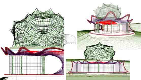
3.1 The Mica Peak Residence (Figure 3):
This 1,600 square foot (148.5 sq.meter) owner-built eco-home is also an opportunity for its occupants to
share with a continuing series of visitors, a wide range of sustainable, salvaged and recycled materials,
techniques and features. It is built into the hillside with an angle-of-slope "vertical crawlspace” behind, with
the roof extending poleward to meet the grade, which eliminates earth pressure against that house-wall,
gives easy access to utilities and provides inexpensive thermally-tempered storage space.
The AGS system is charged by a recessed flat-plate thermosyphon collector, built of salvaged tempered
glass, metal and other materials. The second-story "pilot house" is separable from its open stairs and the
house below, by swing-down glass doors, to prevent heat-losses up the stairs in winter while still providing
natural re-lighting to below. The solar chimney with thermal piston control louvers, behind the pilot-house,
permits totally passive, convective, AGS air-flow. The planted roof-top provides garden space and thermal
buffering above the roof-deck (and doubles the effective energy performance of) the R-35 roof insulation of
14 inch high by 18 inch wide( 35 by 46 cm) straw-bales, fitted between the webs and resting on the flanges
of 18 inch (46 cm) high composite-wood-I-beams at 19.2 inches on center (48.7 cm), with vent space
between the bale tops and underside of the waterproofed deck. The exposure walls are of in-fill straw-bales,
between salvaged-log posts, stuccoed with a mix of onsite sand/clay soil and white Portland cement at a
ratio of 15 to 1 and salvaged windows with track-enclosed baffle night-insulating shades . Other materials of
interest include rammed-earth interior sound-blocking partitions, rammed-earth "cinva" bricks, salvaged
cabinetry and glass block partitions, carpet-over-polysheet-over-earth floors, rice-hull insulation in the shop
roof, tire-bale and earth-rammed-tire retainment walls at shop/garage, artificial annualized-cooling "ice-cave"
walk-in freezer (behind garage into hill) with a high-density load-bearing strawblock (4,500 pounds per linear
foot) separation wall between ice cave and garage, stuccoed salvaged-carpet bank erosion-preventionbarrier, straw-bale sub grade perimeter insulation (between salvaged-carpet-protected polysheet
membranes), all-fluorescent and natural lighting, salvaged windows and light fixtures, salvaged concrete
rubble patio and walk, stuccoed “earth-bag” wing-walls, separated grey-water, solar-pumped well-water
(gravity-fed from up-hill cistern) and grid-tied PVs. This house is in it's third winter of system operation and
dropped to a low of 65 degrees F. (18.33 C.) when unoccupied for several weeks, and its holding-
temperature has improved about 5 degrees F.(~2.8 c.) each winter. (site deep-soil/well temp. 52 F..~11.1 C.)
Figure 3 Figure 4
3.2 The Liberty Lake Residence (Figure 4):
This 1,000 square foot (92.7 sq, meter) contractor-built home above a lake is heated by vertical time-lag
AGS and radiant infloor water tubes the heat of which is recovered from residual AGS heat in garage by an
air-to-water heat-pump water heater. It sits on a plinth of salvaged bead-foam and cement insulatedconcrete-forms (ICFs) surrounding the earth-filled heat-storage vault, which is charged by outside air, preheated in sunward solar collectors with salvaged aluminum-can absorption surfaces and by the heat at the
top of the sunspace, before being fed up into the under-metal-roof plenum for final heating, then drawn down
through insulated ducts into that earth-vault. The sunspace is glazed with salvaged sliding-door-inserts. A
solar sauna adjoining the main bath also provides clothes-drying (and space heat, if desired). "Bottle-wall"
elements in baths use savaged colored wine bottles to provide obscure natural light as do roof suntubes.
The collector metal is only on the east and south faces of the hip-roof, with planted-earth to go on the west
and north and over the underground garage. Interiors are divided by owner-made bamboo and paper
screens. Floors are finished with owner-made paper from onsite weeds, over red-painted floor slab, sealed
with no-VOC urethane. Permeable paving, green roof, rain-catchment planter, plantings and constructed
vernal pool address 100 % of precipitation on site (site will be fully restored to native plantings and pool will
provide ephemeral breeding habitat for amphibians and insects). Sub-surface insulation, berming and rain- catchment planter are of tire-bales and pet-yard retaining wall is of rammed tires. This summer was this
home's first charging season. (Well temperature is nearly the same as Mica Peak Residence, above).
4. Further AGS enhancements, currently in research:
4.1 Heat-pipes and Water Columns
I'm currently exploring minimally-expensive owner-made heat-pipes and polyethylene-barrel water columns,
installed adjoining perimeter walls, extending down about 5 feet (1.5 meters) to intercept heat moving
beyond the structure (below the level where it would otherwise move up through the floor, and draw it up into
the interior wall surface facing the living space, with insulation shutters to make this controllable, on an aswanted basis.
4.2 Annualized Cooling and de-humidification
These have been two long-term goals I share with those in several alternative-building discussion groups,
which continue to receive thought and idea-exchange.
5. Conclusions
As my experience and continuing data collection confirm, with well-designed, energy-retaining structures,
and good collector-area to building volume / heat-loss ratios, AGS system performance over the years can
be expected to keep improving. With careful application, by the third to fifth annual cycle, one may
reasonably expect near 100% solar fractions in most temperate climates, with the balance made up by
incidental indoor heat sources (people, appliances, etc.).
References
Baggs, S., J. & D., 1999, Australian Earth-Covered Building [Book], pub. by New South Wales University
Press Ltd., ~ 200 pp.
Booth, D., 1980, The Double Shell Solar Book, and 1983, Sun /Earth Buffering and Superinsulation [Books],
pub. by Community Builders, ~ 120 and 222 pp.
Butler, L., 1978, Ekose'a Homes - Natural Energy Conserving Designs [Book], pub. by Ekose'a, 78 pp.
Cronkite, W., 2004, "Make Global Warming an Issue", The Philadelphia Enquirer, Mar. 15, 2004.
Dethier, J., 1981, Down To Earth - Adobe Architecture: an old idea, a new future [Book], pub. by Facts On
File, 192 pp.
Disney, W., 1956, The Walt Disney Story of Our Friend the Atom [Book[, pub. by Golden Press, 165 pp.
Gerry, D., 1982, Solar Greenhouses: Underground [Book], pub. by TAB Books Inc., 200 pp.
Hait, J., 1983, Passive Annual Heat Storage - Improving the Design of Earth Shelters [Book], pub. by the
Rocky Mountain Research Center, 152 pp.
Labs, K., 1975, The Architectural Use of Underground Space: Issues and Applications, [Book, from Thesis],
pub. by the author, 192 pp.
Levin, E. 2005, "# 44 - First Campfire Discovered in South Africa", reporting on work by Brain, R. (1988), and
Skinner, A. (2004), Discover Magazine, Vol. 26, No.1, p. 70.
MacKenzie, J., "Oil as a Finite Resource..", World Resource Institute, from the web site:
(www2.gsu.edu/~geohab/pages/geol2001/energy/when_does_global_production_peak.htm)
Maxwell, J.A., 1978, America’s Fascinating Indian Heritage, pub. By Reader’s Digest, 414 pp.
Mazria, E., 1979, The Passive Solar Architecture Book, pub. by Rodale Press, 435 pp.
Pitt, W. R., 2005, "The Prophesy of Oil", at www.truthout.org ,Mar. 7, 2005.
PIPA (Program on International Policy Attitudes), "Public Would Significantly Alter Administration's Budget",
PIPA website, March 7, 2005, www.pipa.org
Steen, B., Steen, A. and Komatsu, Y., 2003, Built by Hand – Vernacular Buildings Around The World [Book],
pub. by Gibbs Smith, Publisher, 469 pp.
STEPHENS, D., (architectural training at the University of Idaho.) www.greenershelter.org
University of Minnesota, Underground Space Association, 1978, Earth Sheltered Housing Design:
Guidelines, examples and References, [Books] pub. by Van Nostrand Reinhold.
 Have there already been situations when young farmers have appeared right next-door to old-school giant monocropping operations? What have the reactions been? 'Although some are threatened by it, overall there's been a big welcoming; most of the older generation are jumping out of their socks to see young people interested in agriculture, even though they're all growing GMO corn.'